Putting 3D In Perspective
Projections, Clipping Planes, and Calculus

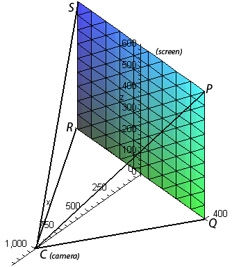
Figure 1: The colored plane represents the viewing screen. The volume of the pyramid is the viewable area.
Introduction
According to question prompt, 3D computer graphics can be rendered by representing objects in XYZ space and introducing a rectangular “viewing plane” or screen, a “camera” point, and four triangular “clipping planes” running from the edges of the screen to the camera. (See Figure 1.) Only objects within the resulting pyramid will be shown by “projecting” them onto the screen for a 2D representation of what the camera “sees;” the rest will be clipped.
Setup
Before tackling any problems, Figure 1 was constructed. The camera C was located at (1000, 0, 0) and the four points of the rectangle representing the viewing plane are located at (0, ±400, 0) and (0, ±400, 600). We shall refer to these four points as P, Q, R, and S clockwise from top-right, as labeled in Figure 1.
Questions
The first question is, “If a line L passes through the points (230, −285, 102) and (860, 105, 264), at would points will L be clipped by the clipping planes?”
First we take the two points and describe L as a parametric vector function:
L = <230 + 630t, −285 + 390t, 102 + 162t>Then generate equations for the left and right clipping planes so we can solve for their intersection with L (if these do not intersect L properly then we will try the top and bottom planes). We find the normal vector to the right clipping plane, nright, by crossing the vectors of the lines CP and CQ. So:
<1000, −400, 0> × <1000, −400, −600> = nright = <240000, 600000, 0>.
The normal vector for the left clipping plane could be found in the same way, or by simply negating the y component of nright, so:
nleft = <240000, −600000, 0>.
Coupling these normal vectors with the point they have in common, the camera point C, yields equations for the (infinite) planes containing the triangular (bounded) clipping planes. The right clipping plane’s equation is:
240000(x − 1000) + 600000(y) + 0(z) = 0
or simplified,
240000(x − 1000) + 600000(y) = 0
And similarly the left clipping plane is:
240000(x − 1000) − 600000(y) = 0
Then we want to find the points of intersection between these planes and our line L. We will call these points P0 and P1, and they are the endpoints for our clipped line. To find them, we plug the values for x, y, and z from the parametric equation of L into the equations of our clipping planes. First the right side:
24
0000(230 + 630t − 1000) + 600000(−285 + 390t) = 0
5520 + 15120t − 24000 − 17100 + 23400t = 0
38520t = 35580
t = 0.9236760125
which needs plugged back into L:
<230 + 630(0.9236760125), −285 + 390(0.9236760125), 102 + 162(0.9236760125)>
P0 = (811.9159, 75.2336, 251.6355)Similarly we solve for the intersection of L and the left clipping plane:
24
0000(230 + 630t − 1000) − 600000(−285 + 390t) = 0
5520 + 15120t − 24000 + 17100 − 23400t = 0
−8280t = 1380
t = −1/6 = −0.1666667
which needs plugged back into L:
<230 + 630(−1/6), −285 + 390(−1/6), 102 + 162(−1/6)>
P1 = (125, −350, 75)At this point we do not know for sure that these are the best answers. We have only assumed the line intersects with the left and right clipping planes before the top and/or bottom. We will check this assumption by attempting to project the clipped line onto the screen.
-
The second question asks, “If the clipped line segment is projected on the screen window, identify the resulting line segment.”
This can be set up as a ratio, based on the x–coordinate.
(Distance from camera for x)/1000
= Fraction of distance from camera for x = (Distance from origin for y or z)/(Projected distance from origin for y or z)Solving for the projected distance:
(Projected y or z) = (Distance in y or z from origin) / (Fraction of distance in x from C)For P0, the x coordinate is 0.8119159 of the way to the camera (where 0.0 would be on the screen). Then it is (1-0.8119159)=0.1880841 of the way from the camera to the screen (where 1.0 would be on the screen). Thus we set the x coordinate to 0 and divide the y and z coordinates in P0 by 0.1880841 to place all three coordinates on the screen, yielding:
P0´ = (0, 75.2336/0.1880841, 251.6355/0.1880841)
P0´ = (0, 400.0, 1337.888)
As you can see, the y component is at 400, or the edge of the screen. This indicates we did a good job finding where L intersected with the right clipping plane. However, since the z component is too large, we know we should have solved for its intersection with the top clipping plane instead. We will correct this error momentarily.For P1, the x coordinate is 0.125 of the way to the camera (where 0.0 would be on the screen). Then it is (1-0.125)=0.875 of the way from the camera to the screen (where 1.0 would be on the screen). Thus we set the x coordinate to 0 and divide the y and z coordinates in P1 by 0.875 to place all three coordinates on the screen, yielding:
P1´ = (0, −350/0.875, 75/0.875)
P1´ = (0, −400, 85.7143)
As you can see, the y component is at −400, or the left edge of the screen, indicating we did a good job finding where L intersected with the right clipping plane. Since the z component is in the range of the screen, then this is indeed a proper endpoint for the projected line.Alright, so our initial answers for P0 and P0´ were incorrect. We could re-solve from the beginning, following the same procedures outlined above with the top clipping plane instead of the right one. Or, we could just look at the yz plane, our projected line, our screen, and see where the projected line hits the top of the screen to get the real endpoint P0´ of the projected line. Here we will opt for the full re-solving method.
The top clipping plane should have the normal vector ntop = CP × CS, or:
<1000, −400, −600> × <1000, −400, −600> = ntop = <480000, 0, 800000>.
The top clipping plane”s equation can then be created from C and ntop:
480000(x − 1000) + 0(y) + 800000(z) = 0
or simplified,
480000(x − 1000) + 800000(z) = 0
Then of course we plug in L again to solve for our new, improved P0.
480000(230 + 630t − 1000) + 800000(102 + 162t) = 0
43200t = 28800
t = 2/3 = 0.6666667
which needs plugged back into L:
<230 + 630(2/3), −285 + 390(2/3), 102 + 162(2/3)>
P0 = (650, −25, 210)Finally we take our new P0 and solve for the projected endpoint P0´.
The x coordinate is 0.65 of the way to the camera (where 0.0 would be on the screen). Then it is (1-0.65)=0.35 of the way from the camera to the screen (where 1.0 would be on the screen). Thus we set the x coordinate to 0 and divide the y and z coordinates in P0 by 0.35 to place all three coordinates on the screen, yielding:
P0´ = (0, −25/0.35, 210/0.35)
P0´ = (0, −71.4286, 600)
As you can see, the z coordinate is 600, or at the top of the screen, and the y component is now in range (between −400 and 400). This indicates we finally did a good job finding the other intersection of L and the clipping planes.
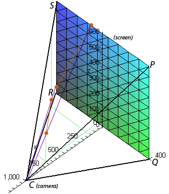
Figure 2: Green lines are used to place the orange endpoints of the orange lines. The line on the screen is the projected line based on the clipped line (which is the one closer to the camera). The purple lines are sight lines connecting the endpoints to each other and camera, showing the projection is correct.
So now our final answers for problems 1) and 2) are:
1) Clipped L runs from (650, −25, 210) to (125, −350, 75)
2) The projected line runs from (0, −71.4286, 600) to (0, −400, 85.7143).
- The third question asks us to verify these numbers by drawing them and connecting their endpoints with sight lines. Figure 2 shows this by placing the endpoints of our clipped line and our projected lines on the graph and drawing lines through them from the camera.
-
There is a fourth question which introduces a rectangle and asks us which portion of L would be obscured by it. While we will not answer this question, we will go over how to solve it:
- Find the equation of the rectangle’s plane.
- Find the intersection of the plane and the rectangle, as we did with the clipping planes earlier.
- Determine which portion of the line (split at the intersection with the rectangle) is behind the rectangle; that is, further from the camera. Call this segment h.
- Calculate the bounds of the rectangle as projected onto the screen.
- Draw the projected line as before, except where h is inside the projected area of the rectangle, do not draw it.